Mastering the Art of Reading a Control Panel Wiring Diagram
In the world of industrial manufacturing and automation, precision and clarity are the foundations of successful engineering. When an electrical control cabinet arrives on the shop floor or is commissioned in the field, technicians, panel builders, and control engineers rely on a single, critical blueprint to understand its inner workings: the control panel wiring diagram. Without a clear and accurate technical drawing, diagnosing a fault, performing scheduled maintenance, or verifying system logic becomes a risky and time-consuming endeavor. For mid-to-late career professionals who value accuracy and efficient workflows, mastering the interpretation of these schematics is essential for maintaining high operational standards.
Yet, reading these diagrams is only half the battle. Modern industrial facilities demand more than just conceptual accuracy; they require physical execution that mirrors the clean logic of the schematic itself. This raises a vital question for modern machine builders and systems integrators: how do you optimize your control panel wiring diagram with a modular control panel frame? By bridging the gap between two-dimensional schematic layouts and three-dimensional aluminum frame assemblies, engineers can create physical panels that are just as legible, organized, and efficient as the documentation guiding them. This comprehensive guide explores the fundamentals of interpreting industrial schematics and demonstrates how advanced mechanical framing elevates your entire wiring workflow.
Deconstructing the Control Panel Wiring Diagram
Before diving into physical assembly or spatial optimization, one must understand the universal language of electrical schematics. A standard control panel wiring diagram acts as a map for electrical current, control signals, and safety logic. It translates abstract engineering concepts into standardized symbols, terminal numbers, and wire tags that guide every connection within the enclosure.
Key Symbols and Conventions
Every industrial schematic relies on a set of universally recognized symbols governed by standards such as IEC or NFPA. Recognizing these symbols instantly is the first step toward efficient troubleshooting:
- Contacts and Relays: Normally open (NO) and normally closed (NC) contacts are represented by distinct bridging or intersecting lines. Understanding their state when the coil is de-energized versus energized prevents costly wiring errors.
- Protection Devices: Fuses, circuit breakers, and thermal overloads feature specific geometric icons indicating their rating and trip characteristics.
- Power Distribution: Main incoming power rails, transformers, and power supplies are typically mapped at the top or left of the diagram, showing how voltage steps down from high-power mains to low-voltage control circuits.
Following Signal Flow and Wire Tagging
Unlike architectural blueprints, electrical schematics are read with a focus on logic and signal flow. In North American applications, ladder diagrams are read from left to right, with power rails on the vertical flanks and individual rungs carrying control logic from sensors to actuators. In European applications, multi-wire and single-line diagrams often follow a top-down convention. Regardless of the regional standard, paying close attention to wire numbers and terminal designations allows technicians to trace a signal from its origin at a PLC input module all the way to a field device on the factory floor.
Bridging Schematic Logic to Physical Layout
A common friction point in industrial manufacturing occurs when the clean, logical flow of a control panel wiring diagram clashes with the physical limitations of the enclosure. Traditional panel building methods, which rely on flat steel backplates, often force technicians to bend, route, and cram wires through congested plastic cable trays. This physical clutter obscures the logical layout shown on the blueprint, making future maintenance difficult and increasing the risk of wiring errors.
To solve this, modern engineers look toward advanced mechanical infrastructure. The integration of a modular control panel frame fundamentally changes how physical components map to your electrical drawings. Instead of treating the backplate as a flat canvas, a modular aluminum frame system allows you to organize components across multiple depths and vertical planes, creating a physical layout that directly reflects the structured hierarchy of your schematic.
How to Optimize Your Control Panel Wiring Diagram with a Modular Control Panel Frame
Optimizing your wiring layout using a modular frame requires a strategic approach that aligns your physical mounting with your electrical documentation. Here is how you can leverage these advanced systems to bring clarity and efficiency to your next project.
1. Grouping Components by Schematic Rungs
When laying out components on aluminum racks within your frame, group devices according to the functional rungs of your control panel wiring diagram. For instance, keep safety relays, emergency stop terminals, and associated contactors physically adjacent on the same horizontal or vertical rack tier. This reduces physical wire length, minimizes voltage drop, and ensures that the physical wiring path is short, direct, and easy to verify against your documentation.
2. Utilizing Multi-Depth Mounting for Cable Separation
Electrical schematics clearly separate high-voltage power circuits from low-voltage control and communication signals to prevent electromagnetic interference (EMI). You can replicate this separation physically by utilizing the multi-depth capabilities of an aluminum frame system. Mount high-power drives and transformers on the primary plane, while positioning delicate sensor wiring and PLC communication modules on an elevated or offset aluminum rack. This physical segregation eliminates cross-talk and keeps your wiring as clean as your schematic.
3. Eliminating Traditional Wire Ducts for Direct Visual Tracing
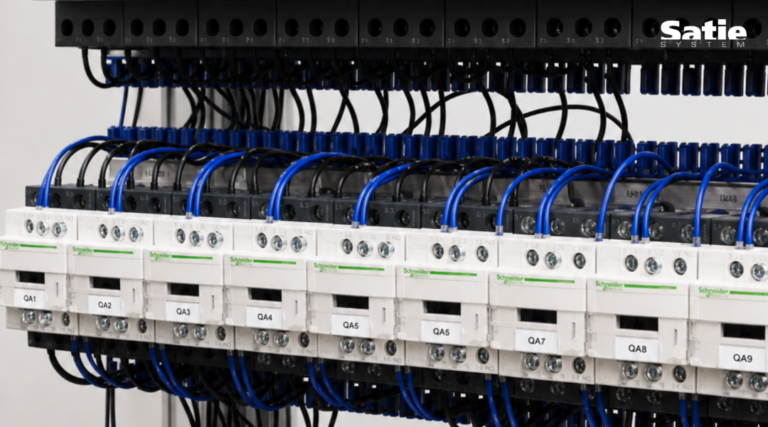
Traditional panels rely heavily on wide plastic wire ducts that hide bundles of wires, turning troubleshooting into a guessing game. When you build with precision-engineered aluminum frames and specialized wire management accessories, you can route cables openly along dedicated aluminum channels. Because every wire is visible and neatly tensioned against the frame, a technician can look at the physical panel and trace a connection visually, just as they would follow a line on the control panel wiring diagram.
The Business Impact: ROI, Efficiency, and Labor Savings
Optimizing your physical control panel layout based on your schematic logic yields measurable operational benefits. For system integrators and machine builders, time is money. Traditional panel preparation requires extensive measuring, drilling, and tapping of steel backplates, followed by tedious wire cutting and duct stuffing.
By transitioning to pre-engineered aluminum framing systems, manufacturers experience a dramatic transformation in workshop efficiency:
- Reduced Labor Hours: Eliminating manual backplate preparation and streamlining wire routing can reduce mechanical installation time by up to 80%, depending on application and workflow.
- Optimized Enclosure Space: Utilizing the third dimension of the cabinet allows engineers to optimize enclosure space by up to 30% to 50%, enabling the use of smaller footprints without sacrificing component density.
- Enhanced Thermal Management: Open aluminum rack designs allow air to circulate freely around high-heat components, preventing hot spots and improving the long-term reliability of sensitive electronics.
These improvements directly address the total cost of ownership, making your manufactured panels more competitive, easier to service, and faster to commission.
Best Practices for Maintaining Diagram and Panel Synchronization
Even the most advanced modular frame will not compensate for outdated documentation. To ensure long-term operational success, maintain strict revision control between your physical panels and your digital assets.
Always update your control panel wiring diagram immediately whenever a field modification or engineering change order (ECO) is executed. Ensure that wire labels match the updated schematic precisely. Furthermore, leverage the precision of your aluminum framing to add laser-engraved or durable thermal-transfer markers directly onto the aluminum racks. When the physical identifiers match the schematic labels perfectly, troubleshooting time drops to a fraction of its former self, protecting your clients from costly downtime.
Conclusion
Mastering how to read and interpret a control panel wiring diagram is a core competency for any industrial automation professional. However, true manufacturing excellence occurs when that logical clarity is translated directly into the physical architecture of the enclosure. By moving away from legacy steel backplates and adopting advanced modular aluminum frame solutions, you can optimize your enclosure space, streamline your wiring paths, and achieve unprecedented assembly efficiency. To discover how our precision-engineered framing solutions can transform your next control panel build, visit Satie System and explore our innovative aluminum wiring management frames today.